USB IKEA DIODER RGB LED Controller
Overview
This page describes an AVR-based USB controller for the nice IKEA DIODER LED strip. The original controller has a single button to choose one of seven colors or to cycle through all of them at full brightness. The new controller is controlled via USB and supports 8-bit resolution for the brightness of each color component. USB support is kindly provided by the ingenious Virtual USB-port for AVR microcontrollers project.
Instructions
Get an IKEA DIODER from the next IKEA - sadly, they don't offer to ship them.
This flickr page describes the innards of the original controller.
Remove the microcontroller in the upper left with a side-cutter to protect the PCB and clean up remaining pieces with the soldering iron.
Then, on a breadboard, build up a basic ATmega8 circuit using the AVR, a 12 Mhz crystal and 2 12-22 pF capacitors (we didn't have caps at home but luckily, the our circuit works even without them - better use them).
The three control lines for the LEDs are connected to PB1-3 as the ATmega8 provides three independent PWM outputs on these pins. On the board, the voltage regulator capacitor C2 is not populate, which makes for a nice 5V power source for the ATmega8.
For the USB connection, we followed the 3.7V Z-Diode approach, but did not connect the USB-VCC as the AVR is already powered by the DIODER power supply.
Software
The firmware for the ATmega is based on the hid-data example for V-USB. The main "challenge" was to figure out how the 3 PWM channels are controlled properly. See PWM_enable() and settingsUpdated() for this detail.
ATmega8 firmware and command line tool
Usage
After being controllable via USB, the next step is to integrate it with an media player to provide an Ambilight (tm) effect for our projector.
The German VDR Project already support similar devices, someone also posted the sources for a xine post plugin.
According to the AtmoWin Wiki entry, there's also support for Atmolights in VLC.
Images

Modified DIODER PCB and new USB controller
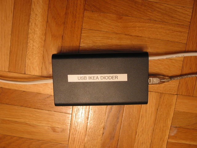
Final box