AVR Light Controller for LiPo/LiIon-Powered Halogen Bike Lights
Motivation
Although super-bright LEDs are superior to halogen lights, as they are more energy-efficient and require smaller batteries, halogen lights are cheaper and easier to build.
In my case, I did already had a Sigma Mirage 6V/20W bike light, but its lead-acid battery is crap, especially in winter when it's cold.
Problem
Lithium-Polymer batteries provide enough power, but cannot be used directly with halogen lights. A two-cell LiPo battery (nominal 7.4V) provides about 8.5V when fully charged, and it is not allowed to be discharged below 5V. Halogen lights are commonly designed for 6V or 12V and their light power is controlled by the provided voltage level. While an 8.5V voltage level can overheat and destroy a 6V halogen light, the emitted light at 5V is very low. Therefore, a power controller is required that keeps the voltage supply constant for the halogen light.
Approach
This project is about building a power controller based on a small microcontroller, here the ATtiny45 was used. The desired output power can be achieved using Pulse-Width Modulation (PWM) of a power source (LiPo battery in this case). The duty cycle of the PWM determines the amount of power sent to a load (i.e., the halogen light).
The resulting effective power of the halogen light is calculated by integrating the applied power over time. With on/off modulation, this results in:
duty cycle = Veff2 / Vbat2
In this project, a microcontroller continuously measures the battery voltage level and calculates the duty cycle to achieve a desired output power.
I've got the basic idea of using PWM for controlling the light voltage by a posting of Willie Hunt in 1993 who later commercialized his designs. Later versions of his initial design already include a Microchip PIC microcontroller. Schematics are available but not the source code for the firmware.
Features
Beside controlling the output power, the use of a microcontroller allows for other goodies:
- Smooth transition between power levels.
- A remote control with a single button and an LED that can be attached for example to the strap of a bike pack.
- The button on the remote allows to turn the light on. It further allows to toggle between BRIGHT and DIMMED power mode. Holding the button for a second turns the light off.
- The control LED warns about low battery or when the light is not connected. Also, holding the input button when the light is off triggers the LED to show the battery voltage level.
Schematic
The schematic for the AVR Light Controller is depicted below.

Schematic for AVR Light Control V1.0
On the left side is the LiPo battery with a fuse and a switch to power off the circuit. Because the Analog-to-Digital-Convertor (ADC) of the ATtiny45 can only measure voltage levels up to 2.55V, a voltage divider consisting of R1 and R2 is used to reduce the battery voltage to 1/8.
R3 and C3 create a low-pass filter. Without this filter, the battery voltage is quite noisy as it drops when the light is turned on, and raises when it is turned off by the PWM.
The 7805 together with C1 and C2 provide the 5V VCC for the ATtiny45. As its idle current is up to 5 mA, the power switch S1 is needed. This is clearly something to change in a later design.
R5, S2, and the LED make up the 'remote control'.
The N-channel MOSFET Q1 is used to implement the PWM, i.e., to switch the light on and off. R7 limits the current to the MOSFET. R8 acts as pull-down resistor to keep the light off when the ATtiny does not work.
R6 is used to measure the drain voltage (VD) of the MOSFET. If the halogen light is broken or gets disconnected, the drain voltage goes to GND. With a working light, VD toggles between Vbat and the small voltage resulting from the resistance of the MOSFET (for a 6V/20W light, it is about 0.4V for the IRF540).
The ATiny45 only requires power supply as it runs from its internal 8 MHz oscillator.
Firmware
The firmware for the AVR Light Controller was developed with the standard AVR-GCC and AVR-LIBC. It is released under GPL v2 or later. During development, a bit-banging software UART was used to output debug messages over PB1, which is used for the LED in the final design. I hope the documentation of the source code is reasonable to understand its workings. In doubt, just ask. The summary.txt file in the archive captured my notes and design decisions during development.
Measuring the drain voltage was a bit tricky as the ADC conversion time is close to the PWM period. Fortunately, the ADC contains a sample-and-hold unit that samples precisely after 1.5 ADC clock cycles. With this, it is possible to setup the ADC and trigger the ADC such that it measures the voltage exactly in the middle of the ON part of the PWM as depicted in the figure below.
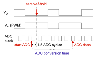
Time diagram for correct measuring of VD
Configuration
The constants in the code are for a 3 cell LiPo battery (nominal 11.1 V) and a 6V halogen light. The 3 cell configuration provides the voltage level for the bright mode almost until the battery is depleted (~7.5V). If you want to use a different battery or a different light you need to check the following three items:
- The voltage divider for battery measurement, i.e., resistors R1 and R2. The ATtiny can only measure up to 2.56 volts. If you change the divider, you also have to adapt the conversion factor from measured voltage to the battery voltage in measure_battery().
- The voltage levels for dimmed and bright mode are set by VOLTAGE_BRIGHT and VOLTAGE_DIMMED respectively. Note that the VOLTAGE_BRIGHT is set higher to compensate for the voltage drop on the MOSFET.
- The voltage level for battery warnings are defined by VOLTAGE_FULL, VOLTAGE_WARN, and VOLTAGE_LOW, which are a function of the number of LiPo cells, NR_LIPO_CELLS. Just set the NR_LIPO_CELLS according to your battery. I've used the following setting for a single LiPo cell: battery low warning below 3.375V, emergency mode below 3.0V in which only the dimmed mode can be used, automatic shut-off below 2.5V.
Implementation
As I wear the light on top of my bike helmet, the battery and the AVR Light Controller are stored in the backpack. In this setup, the remote control (button and LED) are clipped conveniently on the strap of the backpack, instead of dangling around near the light as it is common with commercial Lupine lights. The battery and light controller are packaged together into one box.
Let's show the pictures...
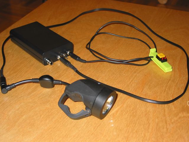
Assembled AVR Light Controller with Sigma Mirage X
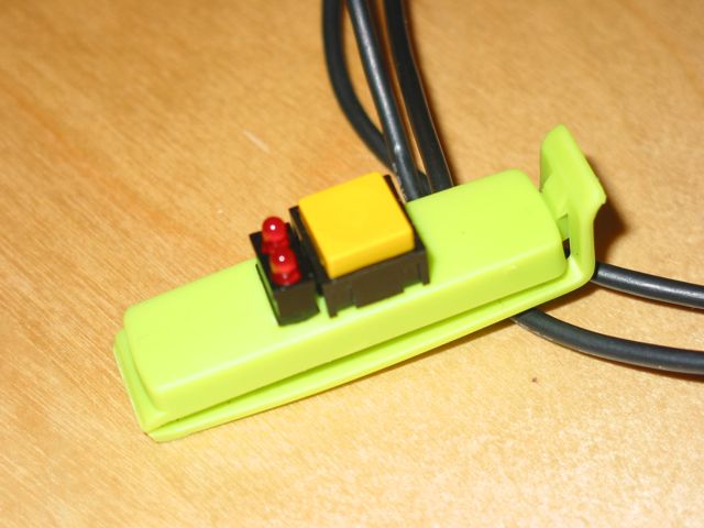
Close-up of Remote Control
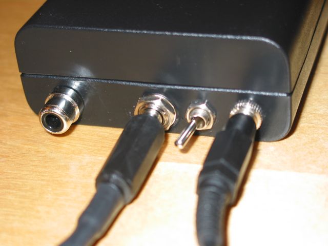
Connectors from left to right: Charge, Halogen Light, and Remote Control. The Power Switch is placed between the Light and Remote Control connectors.
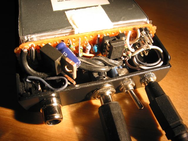
AVR Light Controller circuit
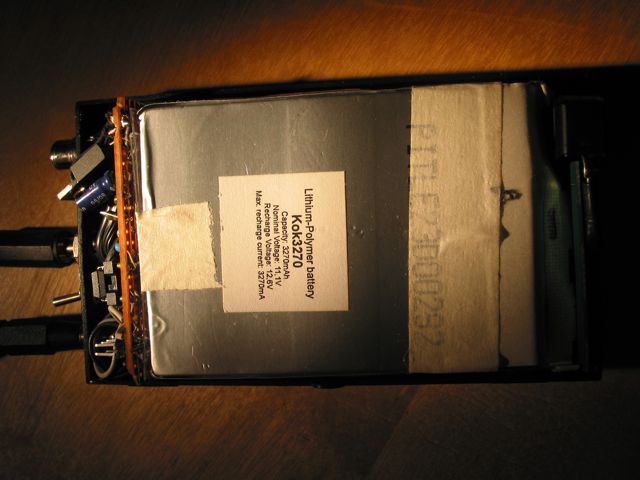
11.1 V, 3270 mAh LiPo Battery => 36 watt-hours
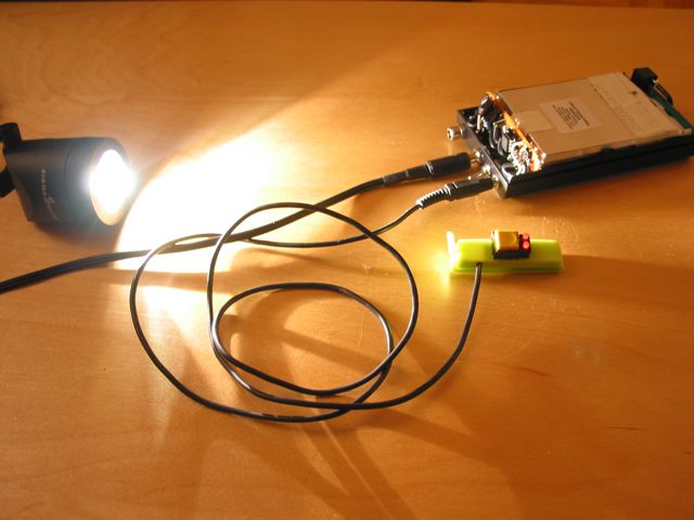
Let there be light!
Links
- Lightbulb Voltage Regulator site of Willi Hunt.
- NightBiken.de provides detailed information (in German) on Halogen Lights and tips for building huge LiPo battery packs. See the LUXILUS and LUXILUS TTR pages.
- Martin Muennich built a similar light controller with an ATmega8 microcontroller, which he also sells in case you are interested in just buying one.